Strip Seal Bridge Expansion Joint
1. Product Overview
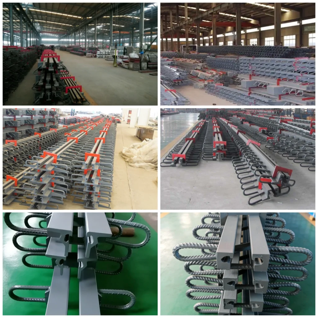
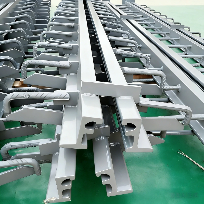
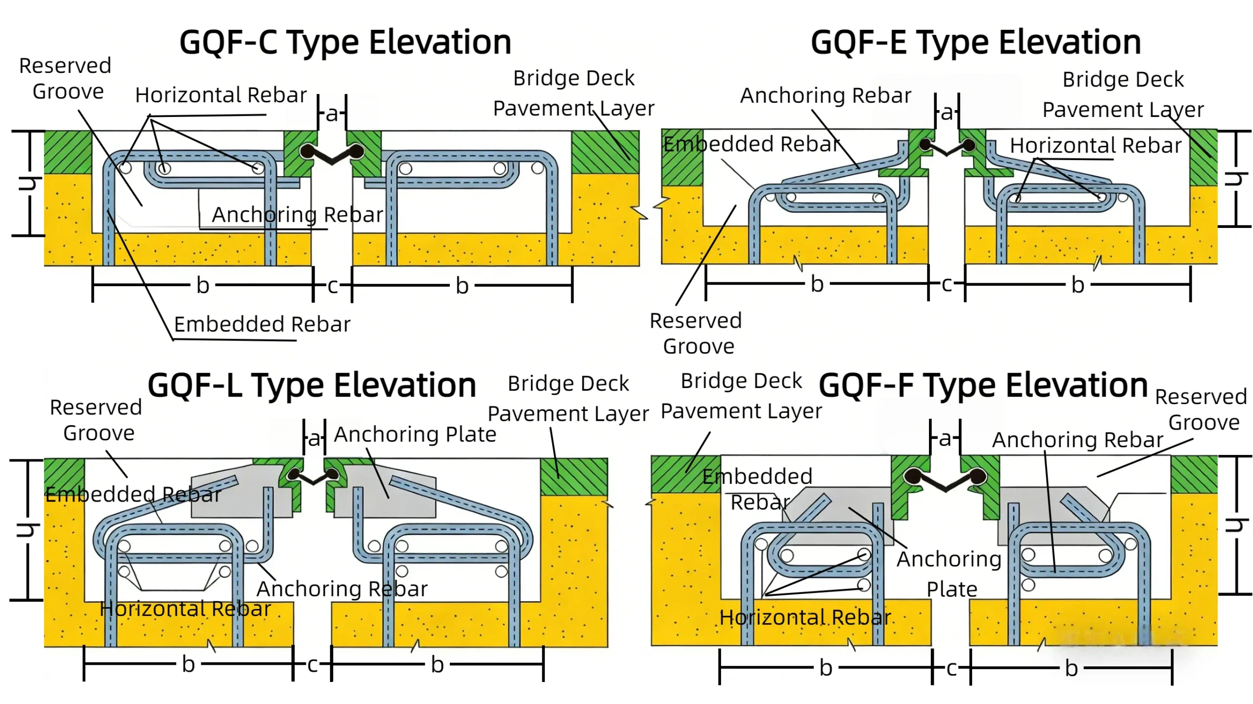
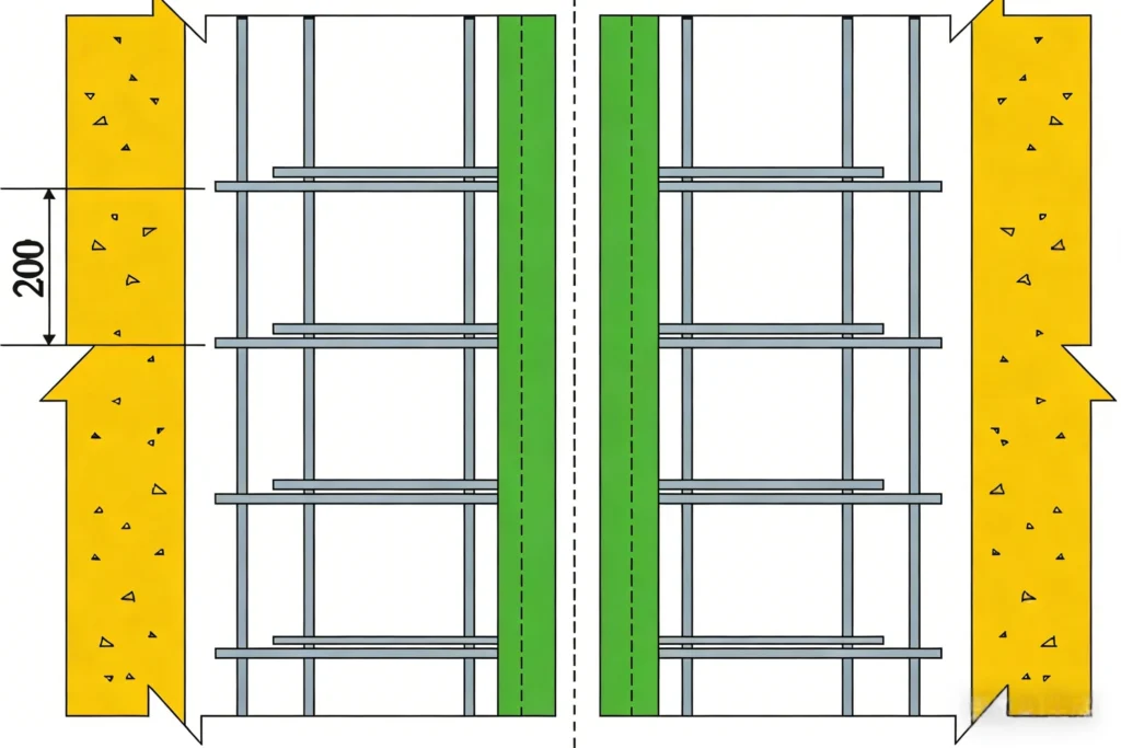
The Strip Seal Bridge Expansion Joint is a single-gap bridge expansion joint composed of two edge beams and a rubber sealing strip. Due to the different types of section steel used, it is available in four variants: Type C, Type E, Type F, and Type L. The structural configuration is shown in the diagram below:
Parameter Table of C/E/F/L Type Strip Seal Bridge Expansion Joints
| Expansion Amount (mm) | Expansion Joint Width a (mm) | Expansion Joint Gap C (mm) | Reserved Concrete Groove Dimensions (mm) | |||
|---|---|---|---|---|---|---|
| amin | amax | Cmin | Cmax | h | b | |
| 20 | 80 | 100 | 14 | 34 | > 100 | ≥ 250 |
| 40 | 80 | 120 | 14 | 54 | > 100 | ≥ 250 |
| 60 | 80 | 140 | 14 | 74 | > 100 | ≥ 260 |
| 80 | 80 | 160 | 14 | 94 | > 100 | ≥ 250 |
2. Key Features of Guchen Strip Seal Expansion Joint
2.1 Performance Parameters of Sealing Rubber Strip for Strip Seal Bridge Expansion Joint
The rubber materials for the sealing strips in Guchen expansion devices fall into three categories:
- Neoprene (CR), applicable for regions with temperatures ranging from -25℃ to 60℃;
- Natural Rubber (NR), applicable for regions with temperatures ranging from -35℃ to 60℃;
- Ethylene Propylene Diene Monomer (EPDM), applicable for regions with temperatures ranging from -40℃ to 60℃.
Hebei Guchen strictly prohibits the use of reclaimed rubber.
| Item | Chloroprene Rubber (Applicable to -25℃ ~ 60℃) | Natural Rubber (Applicable to -40℃ ~ 60℃) | EPDM Rubber (Applicable to -40℃ ~ 60℃) | |||
|---|---|---|---|---|---|---|
| Sealing Rubber Strip (IRHD 55±5) | Rubber Expansion Device (IRHD 60±5) | Sealing Rubber Strip (IRHD 55±5) | Rubber Expansion Device (IRHD 60±5) | Sealing Rubber Strip (IRHD 55±5) | Rubber Expansion Device (IRHD 60±5) | |
| Hardness (IRHD) | 55±5 | 60±5 | 55±5 | 60±5 | 55±5 | 60±5 |
| Tensile Strength (MPa) | ≥15 | – | ≥16 | – | ≥14 | – |
| Elongation at Break (%) | ≥400 | – | ≥400 | – | ≥350 | – |
| Brittleness Temperature (°C) | ≤-40 | – | ≤-60 | – | ≤-60 | – |
| Permanent Compression Set (24h at room temp, %) | ≤20 | – | ≤20 | – | ≤20 | – |
| Ozone Resistance (25-50pphm, 20% elongation, 96h at 40°C) | No cracking | – | No cracking | – | No cracking | – |
| Thermal Air Aging Test (96h at 70°C) – Change in Tensile Strength (%) | ±15 | – | ±16 | – | ±10 | – |
| Thermal Air Aging Test – Change in Elongation (%) | ±25 | – | ±25 | – | ±20 | – |
| Thermal Air Aging Test – Change in Hardness (IRHD) | 0~+10 | – | -5~+10 | – | 0~-10 | – |
| Adhesion Strength Between Rubber and Steel Plate (kN/m) | >7 | – | >7 | – | >7 | – |
| Water Resistance (14d at 23°C, 4% concentration) – Volume Change (%) | ≤+10 | – | ≤+10 | – | ≤+10 | – |
| Water Resistance – Change in Hardness (IRHD) | ≤+10 | – | ≤+10 | – | ≤+10 | – |
| Oil Resistance (No.1 Diesel, 168h at 23°C) – Volume Change (%) | -5~+10 | – | <+45 | – | <+46 | – |
| Oil Resistance – Change in Hardness (IRHD) | -10~+5 | – | <-25 | – | <-25 | – |
2.2 Superior overall performance of the expansion joint
The overall performance requirements of the expansion device are shown in Table 1.
| No. | Item | Modulus/Requirement | |
|---|---|---|---|
| 1 | Maximum horizontal friction resistance during tension and compression (kN/m) | ≤ 4 | |
| 2 | Uniformity of displacement during tension and compression (mm) | Maximum deviation per unit | −2 ~ 2 |
| Maximum total deviation | e ≤ 480: −5 ~ 5 | ||
| 480 < e ≤ 800: −10 ~ 10 | |||
| e > 800: −15 ~ 15 | |||
| 3 | Maximum vertical deviation or deformation during tension and compression (mm) | 1 ~ 2 | |
| 4 | Tension and compression test after relative misalignment (on the premise of satisfying items 1 and 2) | Longitudinal misalignment | The inclination angle of the supporting crossbeam is not less than 2.5° |
| Vertical misalignment | Produces a 5% gradient along the bridge direction | ||
| Transverse misalignment | The difference between the two ends of the two supporting crossbeams within 3.6m is 80mm | ||
| 5 | Determination of central girder stress, crossbeam stress, strain, and horizontal force (simulated braking force) under maximum load | Meet design requirements | |
| 6 | Waterproof performance | No leakage after filling with water for 24h | |
2.3We are a genuine manufacturer of Strip Seal Bridge Expansion Joints with a well-established industrial chain. This enables us to produce high-quality products at a competitive cost for global bridge engineering projects.